Supplement 1.10: Radiation detectors (4/5)
Quantum detectors (3/4)
Photomultipliers
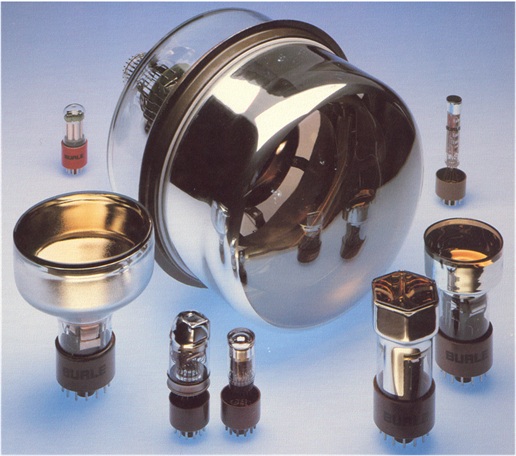
These detectors combine a vacuum photodiode with a high-frequency amplifier in a single tube. The amplifier multiplies the photoelectrons released from the photocathode in several stages and is therefore referred to as a secondary electron multiplier or SEM. The arrangement comprising the photodiode and amplifier is accordingly also known as a photoelectron multiplier, photomultiplier or PMT. They are available in a wide variety of designs, ranging in size from 1 cm to tubes with a diameter of half a metre.
Mathematically, amplification via stages corresponds to a finite divergent geometric series: each subsequent term is multiplied by a factor of 3 to 4. With six to eight amplification stages, this results in an amplification factor of 103 to 105. There are also PMTs with up to 19 stages! The stages are realised using metal plates made of antimony or beryllium oxide (BeO), which are referred to as dynodes. Accelerating voltages are used to direct the photoelectrons or the already multiplied electrons to the respective subsequent dynodes. The kinetic energy of the impact generates further – typically three or four – secondary electrons.
The following diagram shows the basic circuit configuration of a photomultiplier. The resistors and capacitors are soldered directly to the socket terminals to keep the cable lengths as short as possible and thus minimise interference from external electromagnetic fields.
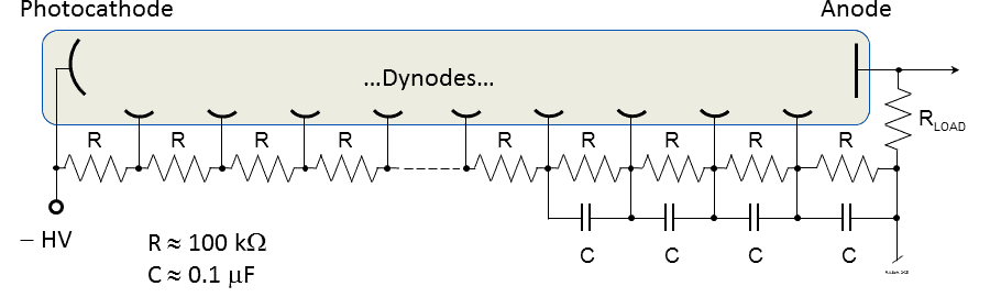
The photocathode is supplied with a negative high voltage (-HV); this is typically between approximately -500 and -1500 V. The anode is connected to ground via the load resistor RLOAD. For pulsed or high-frequency measurements, RLOAD=50 Ω; otherwise, higher values may be used for larger signal voltages. The dynodes receive their voltages via a resistor chain; in this example, the voltages between the dynodes are equal due to the identical resistor values.
The potentials of the last four dynodes are supported by high-voltage-rated fast capacitors (e.g. ceramic capacitors), which is necessary for pulsed measurements. In any case, the dynode currents into the vacuum must not fall within the range of the current in the resistor chain from -HV to zero, as otherwise the potentials of the final dynode stages will collapse. Since the total voltage is maintained by the HV source, the potential differences of the first dynodes would increase, resulting in non-linear amplification.
One advantage of high dynode gain is the ability to count individual photons. An example of this so-called photon counting can be found in a video in the section on photons. The high-amplitude pulses are predominantly caused by photons that eject a photoelectron from the cathode. Smaller pulses are generated by electrons thermally emitted from the dynodes, whose amplification remains lower; this constitutes the dark current already mentioned in relation to vacuum photodiodes. During photon counting, these small pulses are electronically suppressed.
